This article picks up where the UDM Pro setup walkthrough left off. If you haven't done first-time setup yet, start with that article first. Here we configure the network — VLANs, wireless, and firewall policies — to get a smart home-ready network structure in place.
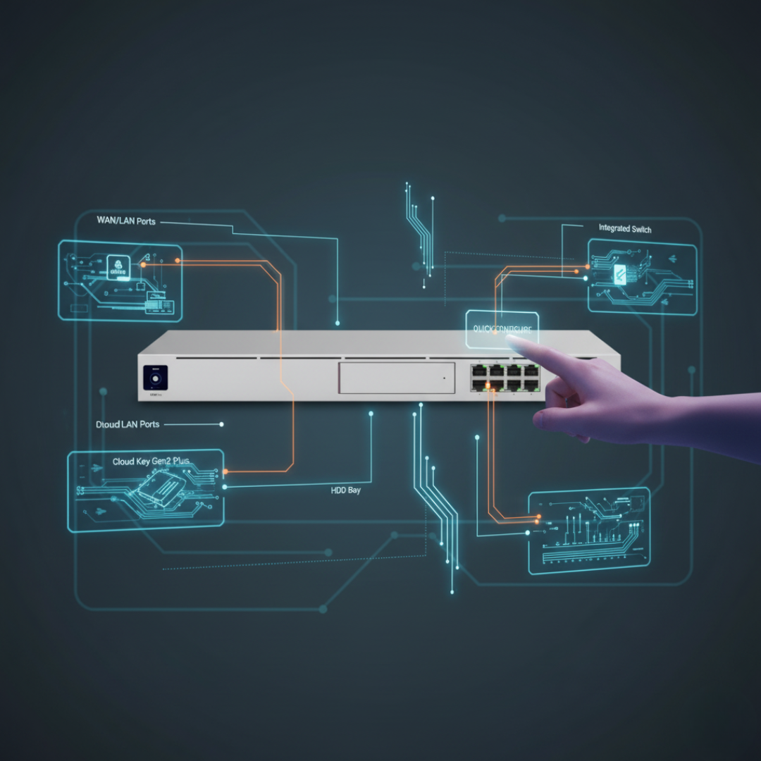
Adopting devices
Ubiquiti devices must be adopted before they can be managed through the UDM Pro. Adoption enrolls the device under the UDM Pro's control and allows configuration through the UniFi interface. To adopt a device, plug it in and power it on, then navigate to UniFi Devices in the dashboard. New devices should appear in a pending state. Click Adopt and wait for the process to complete.
One thing to note: if you're adding an access point, check whether it requires PoE. The Dream Machine Pro's built-in switch ports do not provide PoE — use the included PoE injector or connect through a PoE-capable switch.
Why the default network isn't enough
Out of the box, the UDM Pro creates a single network: 192.168.0.0/24. All devices share this subnet and can communicate with each other freely. For a basic home network this is fine. For a smart home with mixed device types, it creates three problems.
Security: When every device is on the same flat network, every device can reach every other device, including your networking equipment. Anyone who connects to your network — or who plugs into a wall jack — has access to everything. For a home with cameras, smart locks, and access points, that's a meaningful risk.
IP conflicts: Many smart devices ship with a preconfigured default IP in the 192.168.x.x range. If your primary network is also in that range, new devices will conflict with your existing addresses, and the router won't know how to route traffic correctly.
Network saturation: Smart home devices — especially IoT devices — broadcast traffic for discovery. On a single flat network, all of that broadcast traffic hits every device simultaneously. As the device count grows, so does the noise.
Changing the default network
Go to Network Application → Edit the default network. Change the host address from 192.168.0.0 to something in the 10.x.x.x private range. Using 10.20.0.1/24 as an example: this moves the network entirely out of the 192.168 space, avoids conflicts with most factory-default device IPs, and gives you a logical numbering scheme for additional VLANs.
After applying, you'll lose the browser connection — your laptop's old IP address is no longer valid. Unplug and replug the Ethernet cable to get a new DHCP address in the new range, then log back in.
Adding VLANs
With the base network reconfigured, add additional VLANs for different device categories. The process is: Network Application → New Virtual Network. A practical scheme using the 10.20.x.x space:
- VLAN 2 — Wireless / IoT:
10.20.2.1/24. Smart home devices, IoT sensors, voice assistants. - VLAN 3 — Guest:
10.20.3.1/24. Visitors get internet access only — no access to your main network or IoT devices.
Matching the third octet to the VLAN ID (10.20.2.x = VLAN 2, 10.20.3.x = VLAN 3) makes the scheme easy to remember and extend later.
For the guest VLAN, enable Network Isolation — this adds a firewall rule blocking traffic between VLANs. Also disable Multicast DNS on the guest network so IoT devices can't broadcast discovery traffic across that segment.
Creating wireless networks
Go to Wi-Fi and create a new wireless network. Give it a name and password, then under Network, assign it to the VLAN you want it to land in. Clients connecting to that SSID will automatically be placed in the associated VLAN. Repeat for each logical segment — one SSID for your primary devices, one for IoT, one for guests.
For the guest wireless network, also enable Client Device Isolation — this prevents guests from communicating directly with each other on the same network.
Reviewing firewall policies
After creating VLANs with isolation enabled, check the firewall rules that were automatically created. You should see rules for each guest/isolated VLAN blocking traffic to other zones. These confirm that the segmentation is enforced at the firewall level, not just at the network layer.
From here you can extend the segmentation further — add an IoT VLAN with more restrictive internet access, a static-only VLAN for infrastructure devices with no DHCP, or a cameras-only VLAN with no outbound internet. Each segment adds a layer of control and reduces the blast radius if any single device is compromised.